 Larger sea ships are obliged to have radio installations on board;
these radio sets (usually consisting of separate sending and receiving installations) must satisfy very stringent quality requirements set by sea authorities.
The Siemens E566 is an example of a radio approved for this purpose.
Larger sea ships are obliged to have radio installations on board;
these radio sets (usually consisting of separate sending and receiving installations) must satisfy very stringent quality requirements set by sea authorities.
The Siemens E566 is an example of a radio approved for this purpose.
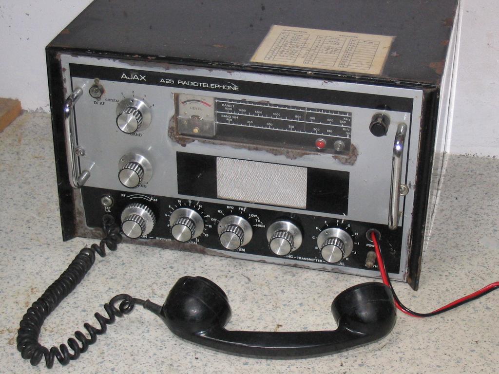
Smaller vessels were not obliged, but permitted to have radio installations. Of course, if you had a transmitter, it should satisfy some type requirements and restrictions on band coverage, precision, transmission power, but these were less severe. The communication set depicted here, the Ajax A25 of 1976, had received type approval for such marine use.
 Inside, the receiving and transmitting unit are quite neatly separated.
The photo on the left is taken from the left side of the dismantled set, and gives a clear view of two of the boards of the receiver unit.
The receiver is a single-conversion unit with RF pre-amplification, two IF stages, and BFO.
The RF board (right) is connected to the triple ganged tuning capacitor, and has nicely arranged antenna, RF, and oscillator coils for each of the three bands.
It contains BF167 (RF amp), BF153 (mixer), and BF153 (oscillator) transistors.
Indeed it is remarkable that a self-oscillating mixer was not used.
I found a schema for the predecessor, a tubed unit A20 with four ECH83 tubes.
That tube unit has a separate oscillator triode, of course, and I found that this transistor unit has a schema that is almost the same as the tube unit!
The IF unit has two amplification stages and also a BFO oscillator.
Under the chassis is a third board with the audio amplifier, including an NKT213 driver and OC35 output transistor.
Inside, the receiving and transmitting unit are quite neatly separated.
The photo on the left is taken from the left side of the dismantled set, and gives a clear view of two of the boards of the receiver unit.
The receiver is a single-conversion unit with RF pre-amplification, two IF stages, and BFO.
The RF board (right) is connected to the triple ganged tuning capacitor, and has nicely arranged antenna, RF, and oscillator coils for each of the three bands.
It contains BF167 (RF amp), BF153 (mixer), and BF153 (oscillator) transistors.
Indeed it is remarkable that a self-oscillating mixer was not used.
I found a schema for the predecessor, a tubed unit A20 with four ECH83 tubes.
That tube unit has a separate oscillator triode, of course, and I found that this transistor unit has a schema that is almost the same as the tube unit!
The IF unit has two amplification stages and also a BFO oscillator.
Under the chassis is a third board with the audio amplifier, including an NKT213 driver and OC35 output transistor.
 In this picture, the front of the set is on top and the receiver section is on the left.
In the top left you see a crystal bank that can hold 22 crystals to allow exact tuning to 22 frequencies.
In each case, the crystal frequency is 470kHz higher than the received frequency, because the crystals control the oscillator, not the antenna circuits.
In this picture, the front of the set is on top and the receiver section is on the left.
In the top left you see a crystal bank that can hold 22 crystals to allow exact tuning to 22 frequencies.
In each case, the crystal frequency is 470kHz higher than the received frequency, because the crystals control the oscillator, not the antenna circuits.
On the right you can see the bottom of the transmitter unit. The lower part has a smaller crystal bank that can hold ten sending crystals. The transmitting crystals have the same frequency as the transmitting frequency. In the inside photo above you can see the transmitter output tube, a 1625, giving approximately 10 Watts of RF output power.
To supply high voltage for the two tubes, there is a voltage upconverter made up of two 2N4280 transistors, mounted on the back of the set. The PL508 is the crystal-controlled oscillator, and its output is amplified by the 1625. Two 97SE128 transistors are the modulator amplifiers, providing plate modulation at the 1625.
 Many of these sets lack the handset, which sometimes causes non-functionality, even in receive mode.
The handset contains a small speaker, a microphone, and a two-poled switch, giving a total of seven leads in the conecting cable.
The switch, when pressed, activates the transmitter and, depending on the configuration, it may also deactivate the receiver.
If the set is configured for duplex mode, the receiver will remain active during transmission, but it is also possible to rewire it so that the receiver is deactivated and in that case a half duplex connection on a single frequency can be made.
Many of these sets lack the handset, which sometimes causes non-functionality, even in receive mode.
The handset contains a small speaker, a microphone, and a two-poled switch, giving a total of seven leads in the conecting cable.
The switch, when pressed, activates the transmitter and, depending on the configuration, it may also deactivate the receiver.
If the set is configured for duplex mode, the receiver will remain active during transmission, but it is also possible to rewire it so that the receiver is deactivated and in that case a half duplex connection on a single frequency can be made.
The wires from the handset are connected to seven lugs in the corner as shown on the photo.
The mike leads, white and blue, are on the top.
Then comes the ear speaker with dark red and green wires.
Then some space and then (for my set) the black lead on lug 5 and both the brown and orange on lug 6.
 I think the variety between the A25 sets is not very large.
As I wrote above, I think it is possible to rewire it for either duplex or half duplex connections, and mine is configured for duplex.
Then, it can be set on either 12V or 24V of power; mine is set on 12V and it takes about 8 or 9 Amps of current when the transmitter is activated.
In receiving mode, the current draw is less than half an Amp.
I think the variety between the A25 sets is not very large.
As I wrote above, I think it is possible to rewire it for either duplex or half duplex connections, and mine is configured for duplex.
Then, it can be set on either 12V or 24V of power; mine is set on 12V and it takes about 8 or 9 Amps of current when the transmitter is activated.
In receiving mode, the current draw is less than half an Amp.
As far as I can see, transmission and receiving frequencies can be selected independently. A little note on the cabinet lists the frequencies for which crystals are provided. Of course, the provided frequencies may differ a little bit depending on where somebody wants to use the set, but the international emergency frequency 2182 kHz is always there, both for sending and for receiving. Remember, that the crystals in the reciving bank have frequencies that are 470kHz higher than the figures on the notes.
The set can be modified to send and receive on other frequencies by putting other crystals.
On the photo above you can see a big air coil, which is the antenna coil for the transmitter.
After changing transmission crystals, the wires need to be placed on other tap places on this coil.

 Claims that a set works are usually taken with a grain of salt by me, but the seller of this set made his story a bit too fantastic.
He said I could take the radio to my car and connect the power leads to the battery, and I would have sound.
Well, would I have taken his advice, I might have been typing without fingers now, because the two leads of the power cable were internally soldered together (photo)!
Regardless of the position of the power swich, any attempt to connect these leads to a car battery would lead to a short immediately and, given the high current a lead battery in a car can supply (over 100 Amps), this is not without danger!
Fortunately I was there by bike and took the set home on my luggage carrier (holding it with one hand).
Home I tried it first with a short circuit resistant power adapter, to find out the set didn't work.
Well, what a surprise!
Claims that a set works are usually taken with a grain of salt by me, but the seller of this set made his story a bit too fantastic.
He said I could take the radio to my car and connect the power leads to the battery, and I would have sound.
Well, would I have taken his advice, I might have been typing without fingers now, because the two leads of the power cable were internally soldered together (photo)!
Regardless of the position of the power swich, any attempt to connect these leads to a car battery would lead to a short immediately and, given the high current a lead battery in a car can supply (over 100 Amps), this is not without danger!
Fortunately I was there by bike and took the set home on my luggage carrier (holding it with one hand).
Home I tried it first with a short circuit resistant power adapter, to find out the set didn't work.
Well, what a surprise!