| Project | AF Amp | Sound |
|---|---|---|
| Ineke's Retro | BC547B | PLAY |
| Matchbox | none | PLAY |
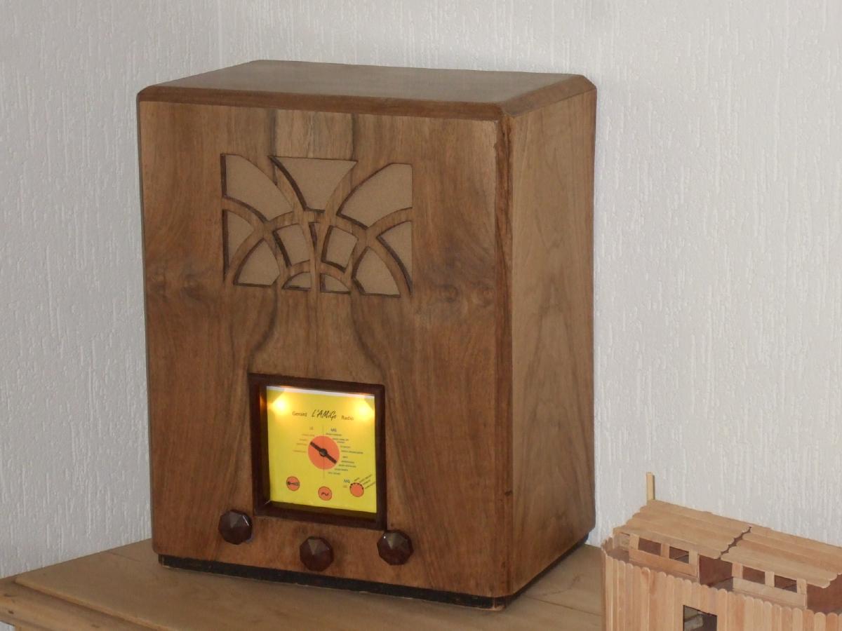
| Gerard L'AMiGo | ECC40, EL41 | PLAY |
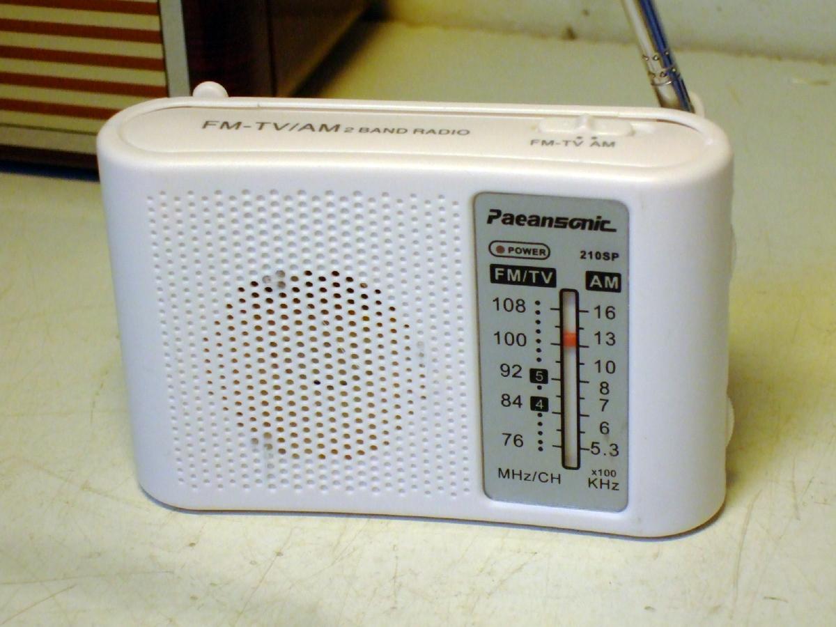
| Paeansonic 210SP | TDA2822 | PLAY |
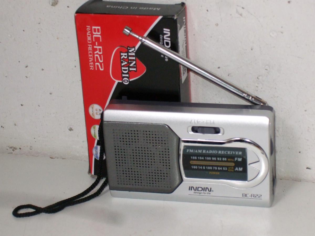
| Indin BC-R22 | TDA2822 | |
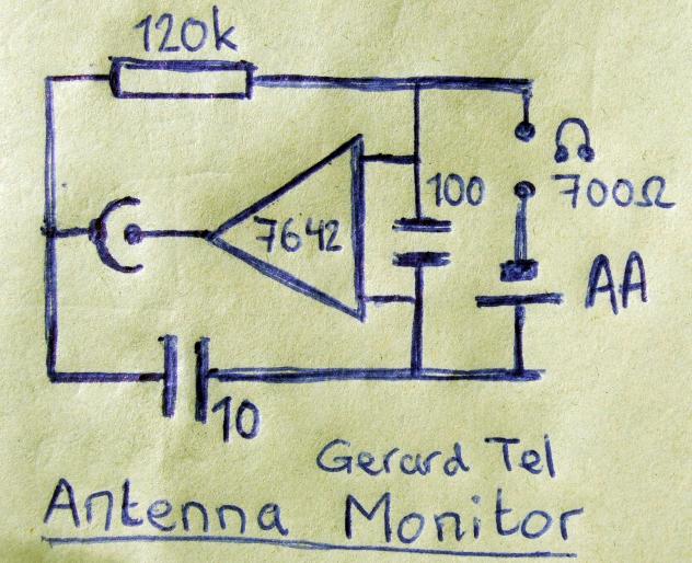
| Loop Antenna Monitor | none | |
| Tubed tuner | LM386 | |
| Pina Colada | BC337 | |
| Matchbox Plus | BC337 | |
| Garden Radio | BC547 |
This article describes the IC and some projects I built with it, and comments on the receiving quality. Some very useful additional information is in this note by Dan McGilles.
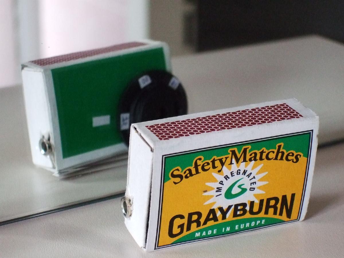
Data sheets of the MK484 are easy to find, but only have two pages with basically little more than the construction of the match box radio. Fortunately, it is as good as equal to the older ZN414 and its sheets can be used. Only be aware of the reversed pin layout!
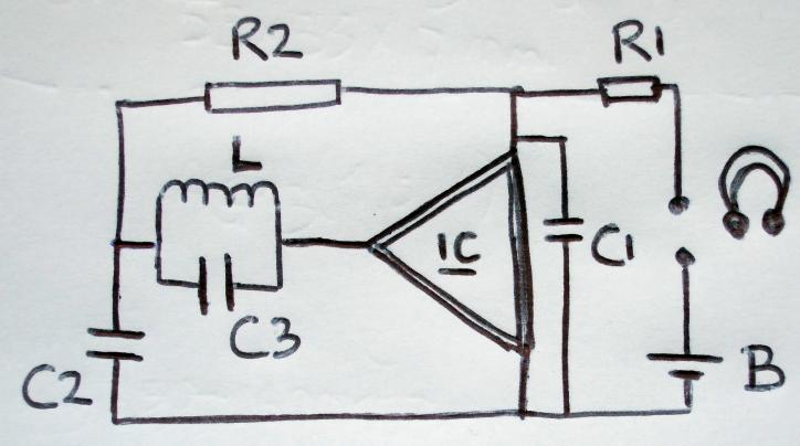 The radio needs, besides the IC, just an LC circuit
of which the coil is also the antenna.
The radio needs, besides the IC, just an LC circuit
of which the coil is also the antenna. The quality factor Q of such a tank is reasonnably high, and so is the input impedance of the IC, giving a fair selectivity. The IC amplifies and detects the AM signal and the current through its output wire has four components. First, a constant DC current of approximately 0.3mA to feed its transistors. The exact value of the DC current depends a little bit on the signal strength, and this was done on purpose; this second, signal strength dependent DC component makes the voltage drop over R1 (800R) signal dependent. Third current component is amplified RF current, which we don't want anywhere on the right side of the chip, so we short it through C1 (100nF). The fourth component is Audio Frequent, which can be taken as current through a transistor amp, or as voltage over R1 for a tube amp.
R2 and C2 form the AGC circuit. R2 (120k) connects one side of the tuned circuit with the DC voltage of the output, so the DC level of the input now depends on the signal strength. Amplification in the IC depends on the DC level, which closes the control loop. We don't want the AGC to react too quickly (it would counteract the modulation), so C2 serves as a buffer.
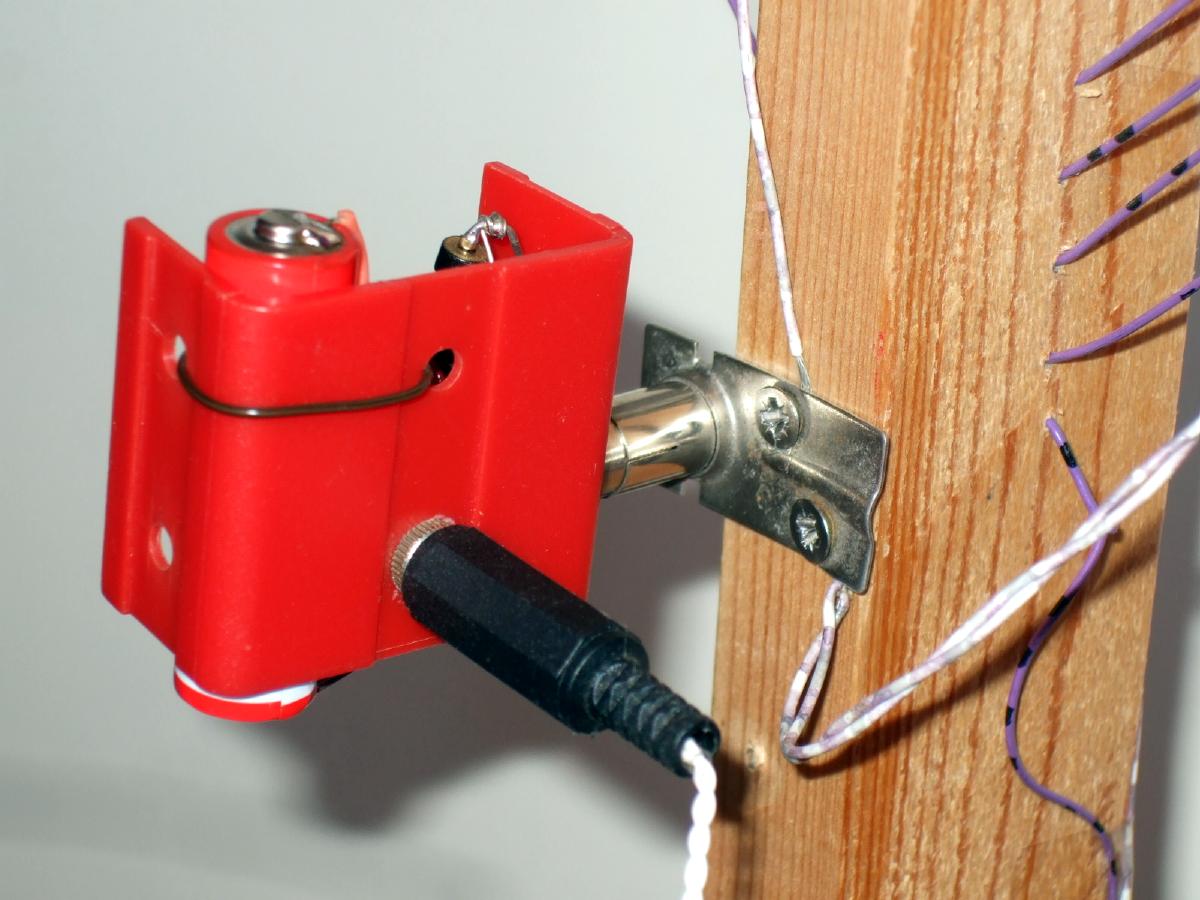
 How is that, being able to check the operation of your antenna
without a real receiver!
This little machine is a bit like the Matchbox,
but without the load resistor and the tuning tank.
Use it with any of my loop antenna's.
How is that, being able to check the operation of your antenna
without a real receiver!
This little machine is a bit like the Matchbox,
but without the load resistor and the tuning tank.
Use it with any of my loop antenna's.
 A more advanced design uses the Tuner IC only as MF stage,
and precedes this with a converter for Short Wave.
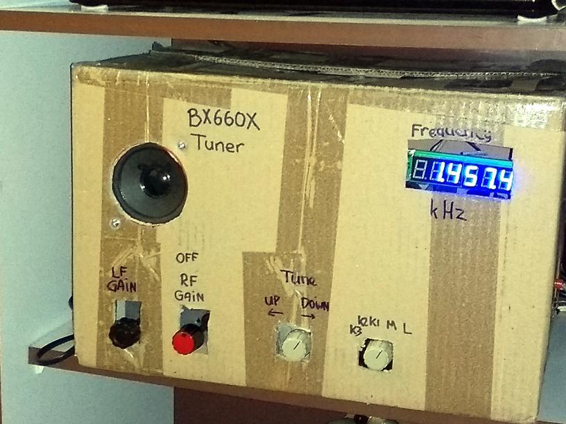
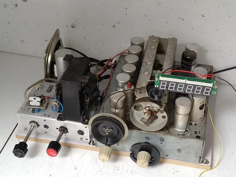
This project uses the tuner of a Philip BX660X of 1946,
then the TA7642 as MF amp and detector,
followed by an LM386 audio amplifier.
I first tried a TDA7297 amplifier,
but that one doesn't have enough voltage gain,
which illustrates the low output level of the TA7642.
By lack of suitable cabinet, the radio project
was first housed in a cardboard box.
A more advanced design uses the Tuner IC only as MF stage,
and precedes this with a converter for Short Wave.
This project uses the tuner of a Philip BX660X of 1946,
then the TA7642 as MF amp and detector,
followed by an LM386 audio amplifier.
I first tried a TDA7297 amplifier,
but that one doesn't have enough voltage gain,
which illustrates the low output level of the TA7642.
By lack of suitable cabinet, the radio project
was first housed in a cardboard box.
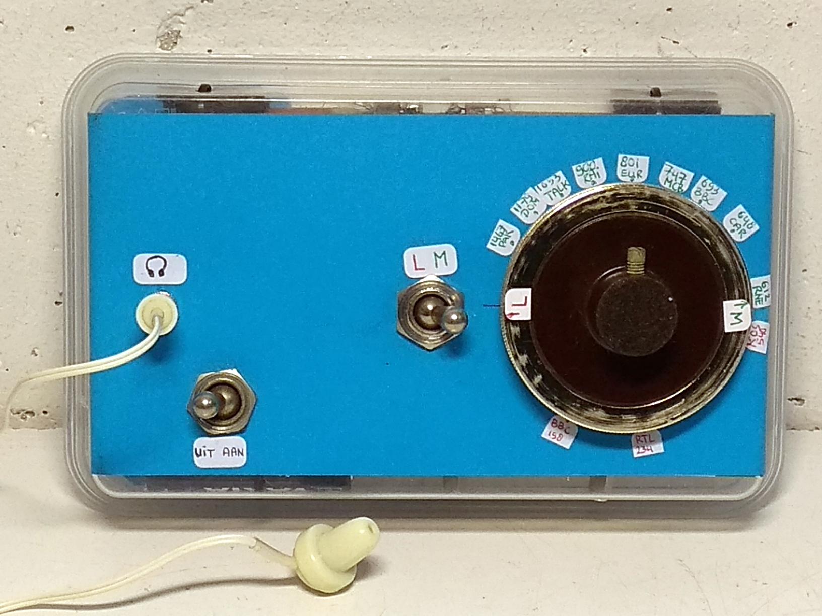 An extension of the Match Box principle,
but with an extra amplification stage
consisting of the BC337.
Long and Medium Wave, power switch,
good reception (10 stations during day and 20 during night)
and even loudspeaker possibilities!
An extension of the Match Box principle,
but with an extra amplification stage
consisting of the BC337.
Long and Medium Wave, power switch,
good reception (10 stations during day and 20 during night)
and even loudspeaker possibilities!

The TA7642 does not work very well on Long Wave,
and in a tiny design such as a matchbox, the switch can be missed.
The Matchbox Plus is almost as small as the Matchbox,
but has an AAA battery soldered in circuit,
and plays loud enough to drive a speaker.
It receives two local stations.
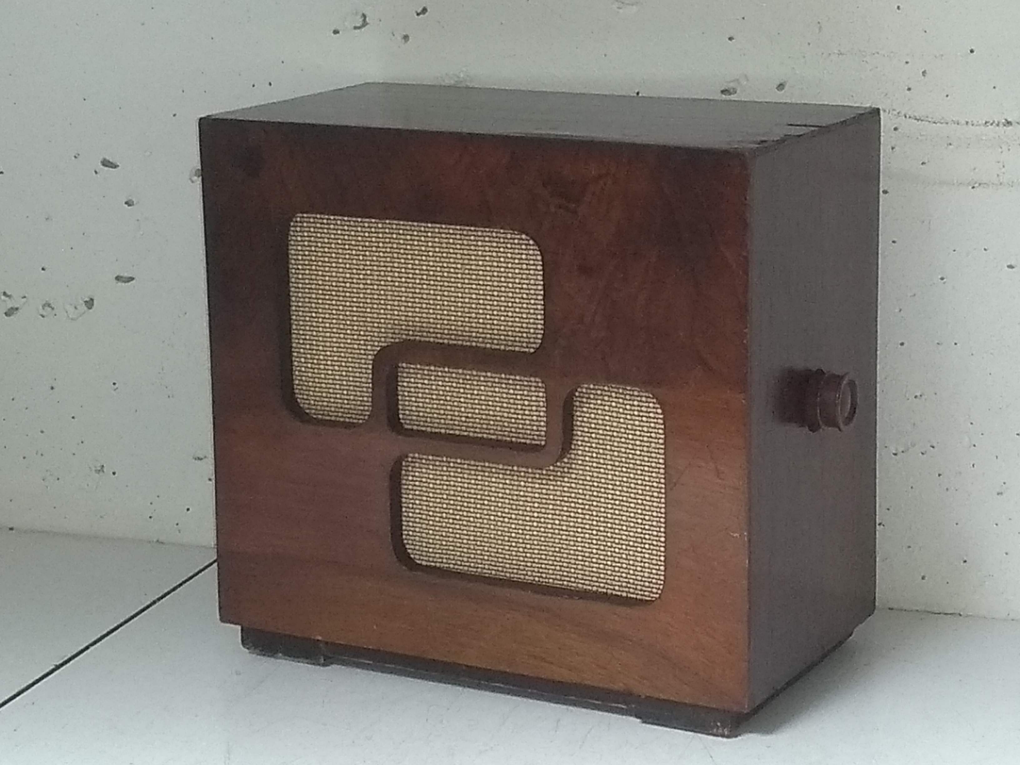 Already with a single transistor as output stage,
matchbox-like radio's can drive a loudspeaker.
I built a TA7642 tuner and output stage
(a BC547 in this case) in the back of an old speaker box
(Plessey, ca. 1947) to enjoy Paradijs and Jinx in my garden.
Already with a single transistor as output stage,
matchbox-like radio's can drive a loudspeaker.
I built a TA7642 tuner and output stage
(a BC547 in this case) in the back of an old speaker box
(Plessey, ca. 1947) to enjoy Paradijs and Jinx in my garden.
Not too much can be expected from the AGC operation. To avoid overloading on strong stations, you should use a large AGC resistor (R2 is 1k) and the supply voltage should be low (1.3V). To avoid noise on weak stations, use a smaller R2 (400R) and/or higher supply voltage (1.6V). To receive strong and weak stations, some manual gain control will be necessary.
Because there is just one tuned circuit, selectivity is limited. If your region has a strong MW station, you may hear it all over the MW band, and it may even mask distant stations. So, your TA7642 project will be a typical local broadcaster receiver.
The antenna coil is hardly loaded by the IC (its input impedance is 4M), and may show a strong directionality. This is nice for handheld or small sets, but a table radio with fixed ferrite rod is not so easy to rotate to optimum reception!
I experience a quite good quality of sound. With my own transmitter, the quality is not limited by the usual 10kHz bandwidth. Also, when a broadcast station comes in with the right signal strength and uninterfered, the sound is good.
The very low output level requires a follow-up
LF amplifier with sufficient gain.
Without amplifier (Matchbox, Antenna Monitor)
the sound is barely audible,
and a tube amp (L'AMiGo) requires three stages.