489
Item nr.

Nicest vintage Bluetooth speaker.
| Production | The Netherlands, 1950.
Price was 198 guilders. |
|---|---|
| Bands | LW (950-2000m), MW (175-580m), SW (15-55m), IF 452kHz. |
| Tubes | Rimlock ECH42 (mixer), EF41 (IF amp), EBC41 (detection, AVC, AF amp), EL41 (output), AZ41 (rectifier), 2x dial light. |
| Cabinet | Wood. |
| Power | AC, 6 voltages, 40W. |
| Documents | Service docs. |
 The Erres KY504 is sometimes referred to as the cheaper companion to the KY505 of the same year. The radio is indeed cheaper at a price of 198 guilders, where the KY505 was 240. But the models were electrically almost the same, and the differences were small. The look of the KY505 is generally highly appreciated, while the KY504 is considered a plain functional wood box. What I like more about the KY505 is that is has all controls in front, where the KY504 has the tone pot and band switch at the side faces. But the 505 has curved wood panels, highly appreciated but expensive to make. Both models had different subversions, by the way: I have seen pictures of the KY504 with dark brown knobs and wood strips.
  With Medium Wave tuning up to 175m, or 1710kHz, the radio covers the American part of the Broadcast band, 1600 to 1700 kiloHertz. Europe used only frequencies up to 1611kHz (and pirates use the spectrum from 1611 to about 1680). The close-up of the dial shows the band coverage (up to 175m), but also some stations considered important by Erres with their assigned channel number in the Copenhague band plan. Erres calls this a "floating dial" because it is only connected at the lower edge, the sides and top edge run completely free.
 Here is a detail of the back panel, showing the tube layout and how to connect aerial and ground. The radio does not have the, quite common but rarely used, extra loudspeaker connection.
| Obtained | 10/2018 from Leo (Utrecht); sn=7971. |
|---|---|
| Condition | 7; works well with new capacitors and wiring, dial and knobs very good, woodwork has some damaged spots, Bluetooth. |
| Value (est.) | 22€. |
| Sound sample | PLAY SOUND With the Broadcast Band (Medium Wave) going as high as 1700kHz, the Erres is able to receive MW pirates. The stations, often from the east of my country, come in quite vaguely. |
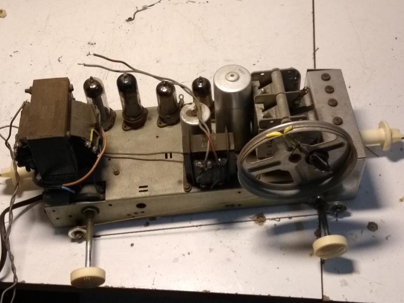 It is good practice to start up old radio's with a series light bulb, but bad practice to keep it there while measuring voltages. I found the B-, supposed to be about -6V, to be only -2.8V and sound distorted! Then my eye fell on the series bulb, which reduces not only B+ voltage, but also heater temperature. Witha 40W in series, B- is 2.8V, with 75W it is -5.0 and without bulb it is -7.3V! The radio really works a lot better then! The chassis view shows the large drive wheel for the tuning capacitor, typical for Erres sets. It also shows the attached coil box at the capacitor end; it is almost as if by accident the chassis was produced too small and some extra box was added.
The power chord was quite a mess, with a screw connection and a switch, while the switching pot was still functional, so I removed all unnecessary stuff there. The tuning drive chord was wound the wrong way around the knob axis: dial and condensator would be properly directed, but you had to turn left to move the pointer right. I rewound the chord according to the service doc, here keep in mind that, seen from the knob, the wire running UP to the condensator is BEHIND the wire running DOWN to the right guidance wheel.
 In March 2020 I installed a Bluetooth unit in this radio, to experience how this feels and do some experiments. So let me relate here how I built in this unit, and what my first experiences are. The work is very easy: I didn't even have to pull the chassis, as the solder connections I needed (heater coil of power transformer) can be reached from behind. The modification was neither very destructive. I soldered two wires to the power transformer (which can be removed again), made a rectangular hole in the back for the unit, and drilled a few small holes in the back for mounting a few peripherals.
  The Bluetooth unit needs 5V of DC to operate, and my idea was of course to use the 6.3V heater supply for getting this DC. Now beware that the unit closes down and resets when the voltage drops under 5V. I had to abandon my plan to use an L7805 regulator, because the rectified heater voltage is too low to provide the 4V voltage gap the L7805 needs.
 So my power supply is a PI-filter, composed of a diode 1N4007, two elco's of 220uF, connected by a 10 Ohm resistor. Diode and both elco's are bridged by 100nF. I was a bit worried that overvoltage might damage the Bluetooth unit, but it turns out that it contains a regulator 78M05 itself, so maybe some overvoltage was foreseen.
 Current draw is about 43mA in Bluetooth mode, up to 60mA in FM mode.
For the FM antenna I provided a Male Coax connector. The picture left shows the arrangement of the unit itself, the antenna connector, the power supply, and the on/off switch.
 The KY504 does not provide a switched pickup enry: as you can see in the schema on the right, the pickup entry is connected directly over the volume potmeter. The low output impedance of the bluetooth unit is supposed to short the signals coming from the detector.
 There appears to be not problem whatsoever with using the radio as a normal radio. If you switch OFF the bluetooth (a small physical switch is provided at the back), the imedance over the output rises to near infinity, releasing the short of the detector signals, and the radio starts giving its normal sounds. Alternatively, you can pull the banana plugs that connect the unit to the pickup entry. The unit keeps operating then, but produces no disturbing radiation.
I am quite pleased with the quality of sound. Not completely surprising, there is some hum when no sound is played from the unit, but when music is played, this isn't really annoying (or even noticable).
 When powered on, the unit is in Bluetooth mode, so the radio can be used immediately as a Bluetooth device without operating the unit; simply connect to BT-SPEAKER.
Pressing Mode switches to FM radio. Try to scan (search and store stations) without antenna to prevent storing weak stations. Once the stations are stored, connect a wire of about 1 meter for good result.
Another press activates the AUX Mode, work as an analogue amplifier from a 3.5mm plug.