371
Item nr.
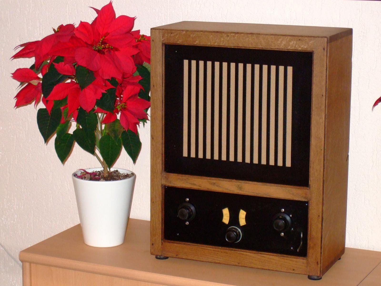
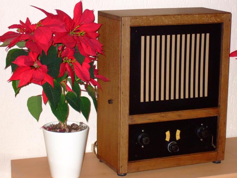
The Singer on the Wall
| Production | The Netherlands, 1930.
Price was 165 guilders. |
|---|---|
| Bands | Lang (LW 450-2000m), Kort (MW 200-550m). |
| Tubes | E442 (HF amp), E428 (Detector), C443 (Output), 506K (Rectifier). |
| Cabinet | Oak wood. Size 38x19x49cm. Weight 11kg. |
| Power | AC 220V, 23W (measured). |
| Documents | Schema (from NVHR, by G. Jongbloed). |
The two tuning condensors are brought out to separate knobs, which must be rotated simultaneously to tune. Why wasn't a dual-gang tuning condenser used? These were available from around 1928. This was discussed at the Radio Cafe on Nov 4, 2014. It was pointed out that with a ganged condenser, synchrony could not be obtained for three reasons. First, alignment between the two caps differs per band as you can see from the tuning table below. Then, the antenna circuit must be corrected for antenna capacity. Third, the detector circuit is influenced by the regen control.
| Station | W | HF | Det |
|---|---|---|---|
| DeutschlFunk | L | 82 | 78 |
| Europe 1 | L | 62 | 59 |
| BBC4 | L | 56 | 54 |
| Polskie R1 | L | 47 | 45 |
| 549kHz | L K | 04 86 | 04 59 |
| R Maria | K | 63 | 45 |
| Nostalgia | K | 55 | 38 |
| Groot Nieuws | K | 35 | 23 |
| DeutschlandF | K | 12 | 07 |
| Obtained | 1/2014
from Pieter; sn=65733  . . |
|---|---|
| Condition | 8. |
| Value (est.) | 150€. |
| Sound sample | PLAY SOUND Leen Jongewaard and Hetty Blok sing this song, that comes out of the Singer very nicely, but in 1967. |

 I just had to pick up the radio with my bike trailer and found it had been in storage in a plastic bag for many years. So, clearly the previous owner had realised that this was a valuable piece.
 But when was it put in storage? The bag was from Didas. Does this give a clue to how long the set was in storage? There was a Didas blanket manufacturer (where Didas stands for Diddens en van Asten) in Helmond, and the Didas logo uses the same letter type as my bag. So, perhaps the radio was stored in a Didas blanket bag of a recently bought blanket. The Textielmuseum estimates the bag from 1965-70; so storage of the set could have happened around 1970 or after.
 Inside the radio, the condensator block is marked 14 nov 1930, which I'll take as the birth day of my radio; I hope to organise a centennial party and play the radio on November 14, 2030. Hardly visible was an inscription made with a knife on the back: ALS AANDENKEN AAN MIJN LIEVE MOEDER (as a remembrance to my beloved mother). Perhaps the radio was inherited from the mother, or bought with money inherited from her.

 The power chord was completely crumbled and unsafe, so I decided I should visit the NVHR Swap Market first, to get new chord. Indeed, on February 23 I found a perfect power cable, that even had a third wire that I could peel off and use as an antenna. Then I could open the radio and unmantle everything. On the right you see the speaker, type Philips 2044, and the dusty top of the receiving chassis.
 The radio was not exactly clean. During significant parts of the twentieth century, smoking in a house near vulnerable children and radios, was an accepted habit. If you want to know what this does to your kids' lungs, look at the left photo of the aluminium back plate, after cleansing one half of it. Also the wood cabinet and chassis were covered in brown layers of dirt.

 I decided to work on the power supply unit (a separate chassis in the top side of the cabinet) first, because good power supply is essential for safe operation. The capacitor blocks contain C1 through C4, paper capacitors in wax of capacity 4 to 6 uF. I do not consider these very reliable (though I heard that those from 1930 may easily outlast the notorious tar capacitors of the forties and early fifties), so decided to replace them by electrolytes. Only later I realised, that ordinary capacitors would have been a better choice; they are available in the multi-microFarad range, and have practically indefinite life span.

 I dismantled the blocks, took out the tar and old guts. If you put the blocks in hot water for a while, the tar becomes a little bit soft so you can take it out more easily.

 The new capacitors are a lot smaller, so the capacitor blocks are mostly empty now. Meanwhile I started also to work on the cabinet. I removed the loudspeaker plate and cleaned the wood with hot water and washing soda. A lot of dirt came off and it made the cabinet look a lot lighter.

 The receiver chassis has three tubes, two coils and just a handful of other components. After placing the tubes and the power plug I only heard a very soft noise. It turned out R1 (cathode resistor of the HF tube) was interrupted, and this I could fix easily. Then the radio worked, albeit still rather softly.
 I tried several options to get louder sound, but to no avail. The output tube C443 is worn out considerably (its plate current is only 7mA instead of 15mA) and I think this is the main cause of the soft sound. A test with a PC86 (photo right) revealed that the C443 can be successfully replaced by such a (abundantly availably) tube. And, with such a despair tube, the radio might even sound better!

 The metal plate that shields the chassis has the serial number, and some space for licence information, but nothing can be read there. The speaker cloth is rather discolored and I replaced it by fresh cloth (from Margot's treasure cave).
 After remounting the speaker board and speaker, the power supply and receiver chassis can be put back in the cabinet. Meanwhile I found replacements for the output tube and the rectifier, and the old tube go in the basement as spares.
 If you compare these two photo's, you can see how dirty the cabinet was before I started cleaning it.
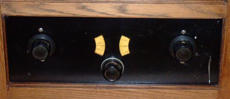 foreign stations, you'll need a long outdoor antenna. Plug the receiver to power, and ask everybody to shut up. Select the desired band (K or L) and set the HF dial (left) to the approximate frequency. The find the station with the Detector dial (right), keeping Regen (middle) close to generation. After finding the station, adjust HF to maximum volume and Regen to the desired level of selectivity and sensitivity. Adjust volume (left side panel) to most pleasant listening level.