245
Item nr.
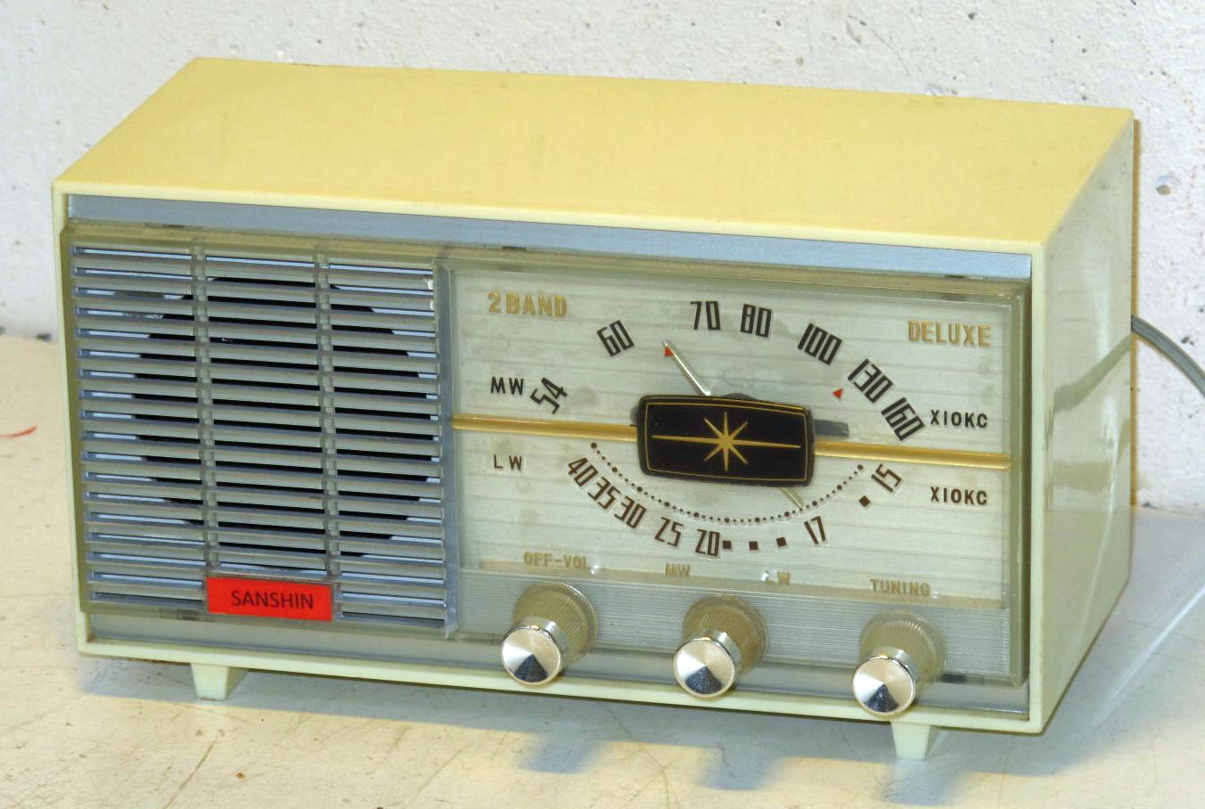
Two band extremely small tube radio
| Production | Japan, 1963.
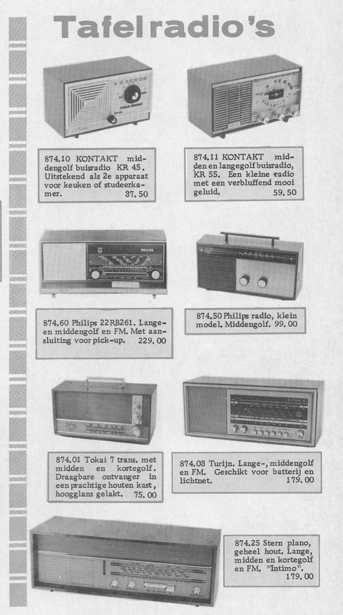
Price was fl 59,50. |
|---|---|
| Bands | LW (150-400kHz), MW (540-1610kHz); IF 455kHz. |
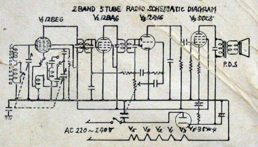
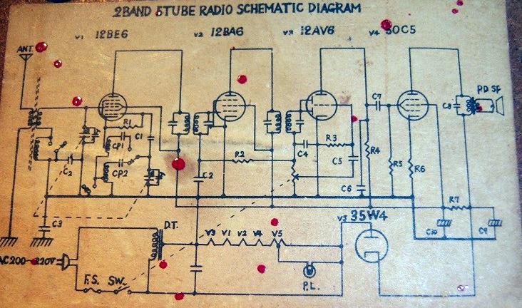
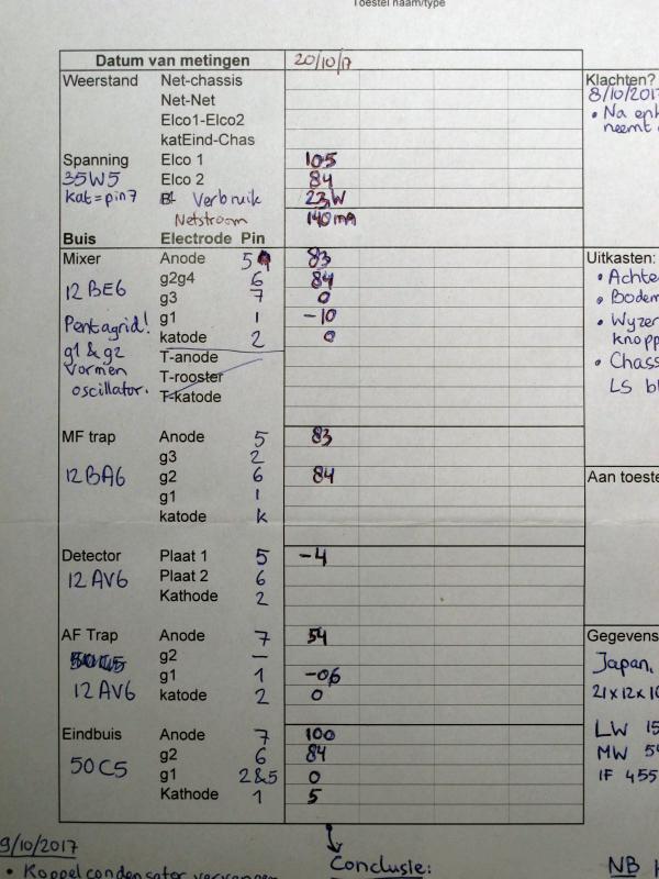
| Tubes | 12BE6, 12BA6, 12AV6, 50C5, 35W4. |
| Cabinet | Plastic. Size 21x11x11 cm. Weight 1.6 kg. |
| Power | AC 220V50Hz (line frequency matters because of capacitive dropper); consumption 140mA/23W. |
| Documents | Schema (on back), Advertisement (1967), Radiomuseum. |
The radio is very similar to this Salofe radio, but a bit less extremely small. It is also equiped with a condensator in the heater chain to avoid heat development in the small cabinet. Because of this capacitor dropper, the heater current will become too big if you run it on 60Hz power.
 Several companies in Europa (and the US) imported these very cheap radio's from Japan, and also they could have them made by their own specifications. To adapt the radio, built for 115V AC in Japan, to the European 220V mains, different solutions were used. My radio has a series capacitor in the heater chain, as in this Schema, but some othe companies requested an auto transformer, like in this schema.
The name decals were not glued very durably, and most sets nowadays come without the name. So I do not know if my set (with series capacitor) it the one listed in the Kontakt advertisement on the left for fl 59,50.
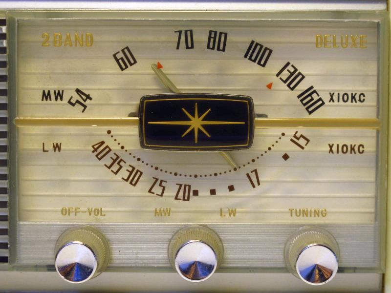 It has a very nice backpainted dial. At 640 and 1240 kHz you'll find Conelrad markings, which were obligatory in the US between 1953 and 1963, but placed on most export models by Japanese manufacturers. Station names are not common on radio's imported from Japan or the US.
Two warnings to those who want to operate such a set: First, the dropper condensator is a paper cap, which can seriously wear out and damage the heaters of the tubes! Because of increased capacity or leakage, the heater current becomes too large. So replace this cap or at least check it! Second, the knobs come of quite easily after which you can touch the chassis. Normally this isn't directly connected to the line voltage, but in practice it almost is. The connecting capacitor of 50nF can pass lethal currents, it may be leaking to pass extra current, or some other component may have damaged insulation. Be sure to use this radio only with knobs and see that the chassis cannot be touched anywhere!
| Obtained | 9/2004 from Boris Algra. |
|---|---|
| Condition | 8. |
| Disposed | Sold 12/2019. |
| Sound sample | PLAY SOUND Golden Oldie, recorded from Ruud's Radio Paradijs. |
 It is almost fully complete, it only misses a small decal with its name on the front. I informed about the color, this was originally red and I just printed that name SANSHIN on red paper and glued it in place. Futaba is the brand of the tubes inside, the set was made in Japan and probably sold under a brand name like Aurora or Kontakt.
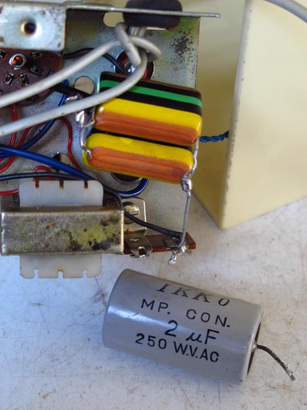
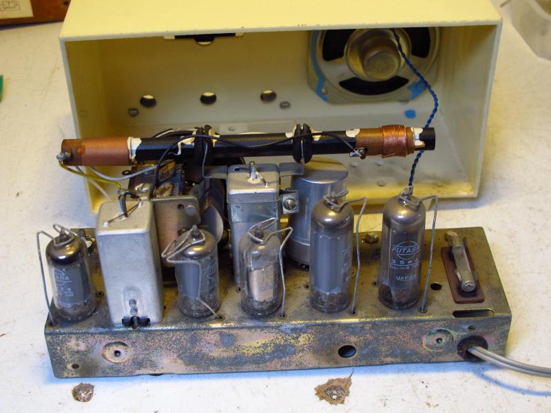
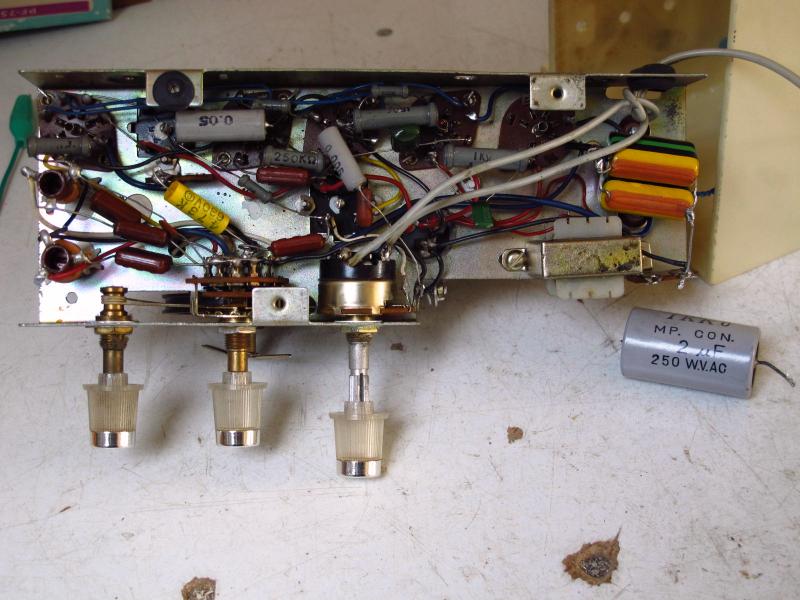 When I opened and measured the radio for the first time (after owning it for 13 years), I found out that the series capacitor had changed its value dramatically. From 2uF it had increased to 2.5uF, with considerable leak and it became hot after a few minutes. So I replaced it by two 1000nF caps in parallel (photo left). Having the set open, I also replaced three more capacitors and measured the voltages on all tubes, which appeared to be fine. With 105V/85V on the filter caps, the B+ looks a bit too low, but the radio plays very well so this is probably not a big deal.
 In December 2019 I found the insulation of the power chord damaged. The radio was sold to somebody who had possessed this model in 1968.