385
Item nr.
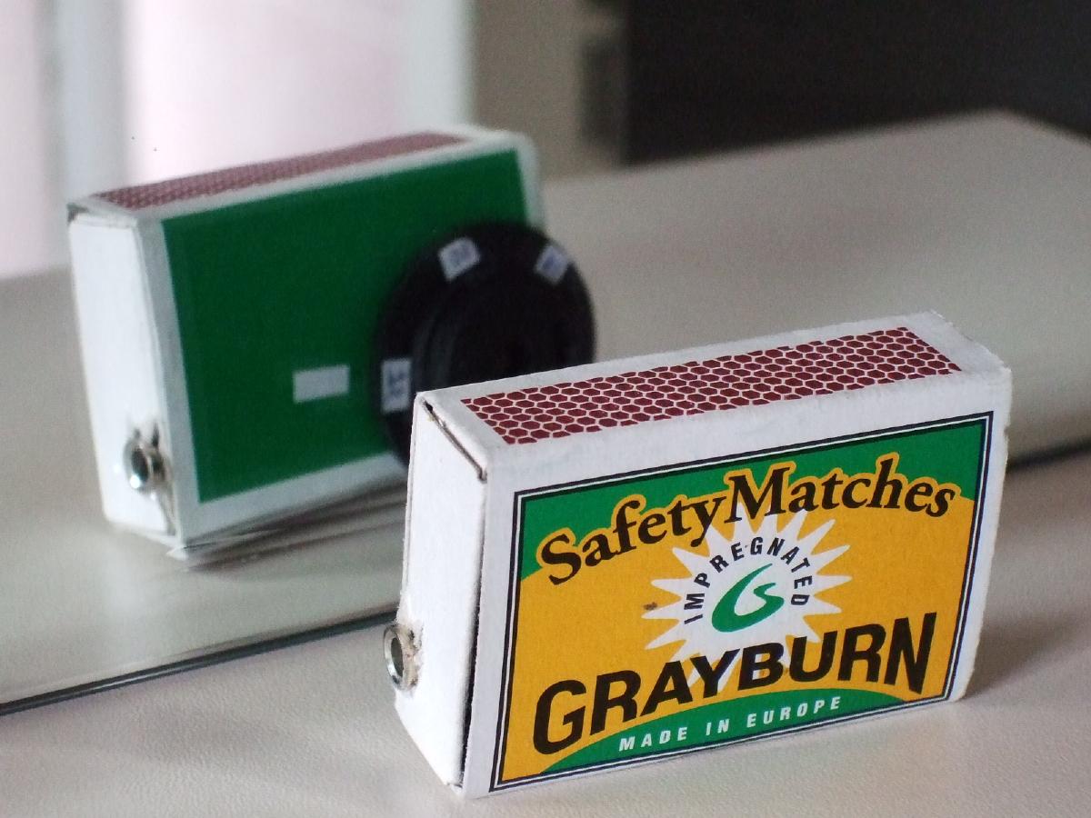
My first MK484 project
| Production | The Netherlands, 2015.
Price was 1 €. |
|---|---|
| Bands | MW (750-1600kHz). |
| Semi- conductors | MK484 (tuner IC). |
| Cabinet | Matchbox. Size 53x35x17mm. Weight 24gr. |
| Power | Batt AG13 (1,5V). |
| Documents | schema. |
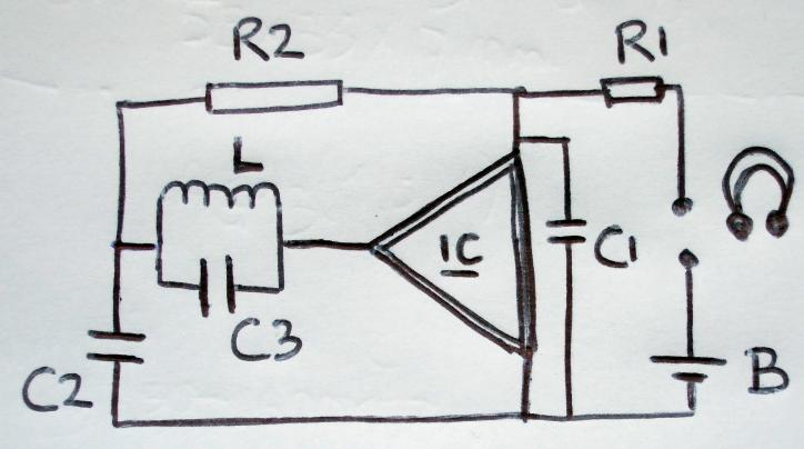 The radio has only one tuned circuit, formed by ferrite rod L and tuning cap C3 taken from a donor radio. The quality factor Q of such a tank is reasonnably high, and so is the input impedance of the IC, giving a fair selectivity. The IC amplifies and detects the AM signal and the current through its output wire has four components. First, a constant DC current of approximately 0.3mA to feed its transistors. The exact value of the DC current depends a little bit on the signal strength, and this was done on purpose; this second, signal strength dependent DC component makes the voltage drop over R1 (800R) signal dependent. Third current component is amplified RF current, which we don't want anywhere on the right side of the chip, so we short it through C1 (100nF). The fourth component is Audio Frequent, which is what we want in our earphone so we let it run freely through the ear jack (together with the DC which does not hurt the ear piece in this small amount). R2 and C2 form the AGC circuit. R2 (120k) connects one side of the tuned circuit with the DC voltage of the output, so the DC level of the input now depends on the signal strength. Amplification in the IC depends on the DC level, which closes the control loop. We don't want the AGC to react too quickly (it would counteract the modulation as in my defective Spidola), so C2 serves as a buffer. For C2 10nF would be enough, but I have 33nF there which makes the AGC react a bit slower. For R1, 120 Ohms is not enough; the overall voltage on the IC is too high so it overloads on strong stations, and the voltage decrease is too small for weak stations so they remain weak. Set R1 to 800 Ohms for better AGC operation, but the audio in a 32R headset becomes rather weak.
The battery is an AG13 button cell, with a capacity of around 50mAh, but because the IC takes only 0.3mA it could last some 100 to 150 hours. Probably more than you will ever use the radio, so I expect the battery to die of aging, not of running out. The radio is switched on and off by inserting the headphone jack and removing it (cutting the battery off completely). To replace the battery, open the box (tuning axis slides through a cut in the outer box) and tape a fresh 1.5V cell between the red and blue wire.
| Obtained | 1/2015 from scrap parts (from Micro radio). |
|---|---|
| Condition | 8. |
| Disposed | Storage (inquire if interested to buy). |
| Sound sample | PLAY SOUND On January 7, 2015, twelve persons were killed at the Paris based magazine Charlie Hebdo, and this attack was followed by a chase and a hostage in a Jewish supermarked. The sound is a little distorted for strong stations, but Groot Nieuws Radio sounds quite OK through the ear phone. Recording directly from an ear piece is the main sound killer here. |

 When you start glueing the connector, screwing the tuning cap, and taping the antenna in a matchbox, you find out how small a matchbox really is! Then solder the other parts in place. The battery is a small button cell, taped to a red and blue connector wire.
 After pushing very hard and squeezing the whole machinery in the box, I attached the tuning wheel on the back and marked the three Dutch stations on the wheel (75, 10, and 16 for 747AM, 1008AM, and 1584AM).
Vulnerable spot of the set is the taped connection of the battery leads. In 2021, I found a reasonable workout by placing the battery in a shrink wrap, which keeps the leads better in place. I also added a BC337 amplifier to increase sound level.