512
Item nr.
Movable set with built in antenna's.
| Production | The Netherlands, 1951.
Price was fl 162. |
|---|---|
| Bands | LW (1150-2000m), MW (185-580m), SW (16.5-50m). |
| Tubes | UCH42, UF41, UBC41, UL41, UY41; dial lamp 8097D. |
| Cabinet | Bakelite. Size 29x18x15cm. |
| Power | ACDC 127/220V, 43W. |
| Documents | Service docs. |
Subtype -10 refers to the color of the cabinet and knobs.
| Obtained | 4/2020 from Cheops; sn=L9236. |
|---|---|
| Condition | 9. |
| Value (est.) | 22€. |
 except that a previous repairer had forgotten to connect the speaker, and miswired the dial chord. You can see here that the chassis is in very neat condition, I just dusted it a bit. On the back side of the chassis you can see the somewhat uncommon type of loop aerial, with just a single turn.
  As a routine measure, I replace a few capacitors in ACDC sets: C29 (coupling cap), C30 (Boucherot) by 20n, C12 (AVC) by 40n, C34 (ground connector) by 4n7 X1 safety, C3 (antenna) by 2 of 2n2 X1 cap in series, C27 (tone correction), C31 (signal), C21 (rattling) bij 22n at 1000V.
The radio can run very hot on the top side, because (operating on 220V) it dissipates 43W nominally. Dissipation (energy consumption of the set) is reduced a lot when you replace R3/R4/R5 by a capacitor of 1.5uF, so that's what I did; it saves about 12 Watts. You can see the red ballast capacitor in the right upper corner of this chassis picture. Another energy-saving modifivation is replacement of the kathode resistor of B4, replace 150 Ohms by 220 Ohms, which saves about 2 Watts.

 The service documentation has an erroneous picture for the dial string (left). If you would string the dial like this (and connect the pointer to the upper wire), the indication by the dial is reversed! That is, while the dial listst shorter waves on the left, you'd have turn to the right to receive the stations with shorter wavelengths. I consider it almost certain, that the radios leaving the factory were correctly stringed, but later repairs were probably done using this diagram, leading to dial misconfiguration. A quick fix would be, to connect the dial pointer to the lower wire, after which it will point correctly. But rotating the dial knob to the right would move the pointer to the left. A better fix is to string the chord correctly, that is, using the diagram in the docs of model BX221U (right). As you can figure out by following the wires, in the wrong picture the tuning cap rotates in the other direction as the tuning knob while in the correct picture, knob and capacitor move in the same direction.

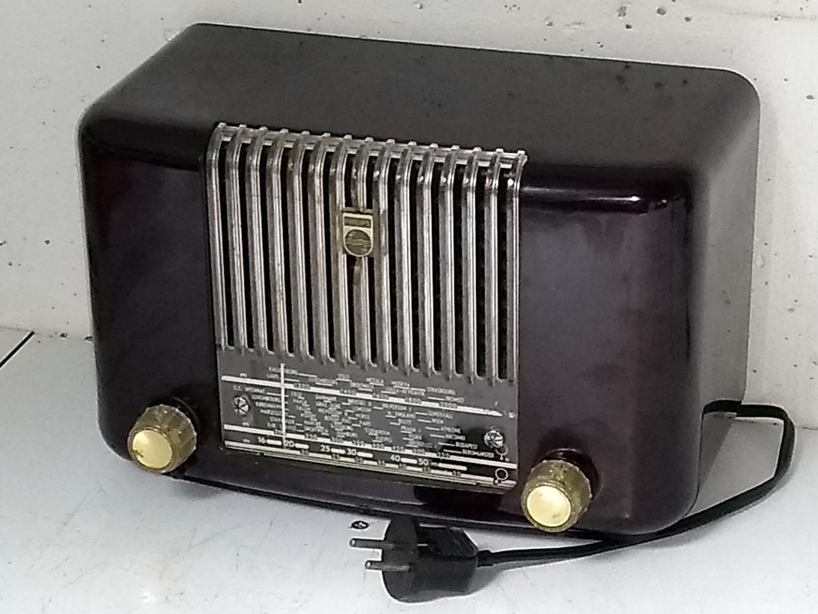
 The dial and speaker grille were a bit dirty, so I did some careful cleaning with water and ear tips. You should be careful not to touch the dial lettering with water, because it damages very easily. Half way the cleansing I took a picture of the dial, and if you cannot see which half I already did, probably some of my work was superfluous. Right is a picture of the radio when I got it.