310
Item nr.

The Shortwave listener's pride of the turn of the century.
| Production | The Netherlands, 1949.
Price was 360 guilders. |
|---|---|
| Bands | LW (715-2000m) MW (185-580m) 4xSW (32-50.5m, 21.5-32m, 17-26m, 13.5-20m). |
| Tubes | ECH21(osc. and mixer), EAF42 (IF stage and avc diode), EAF42 (detector and audio preamp), EBL21 (output tube), AZ1 (rectifier), EM34 (tuning indicator). |
| Cabinet | Wood. Size 50x34x24 cm. Weight 10,5 kg. |
| Power | AC 50W. |
 Examples of these include the BX690A and BX591A. They were quite good receivers for broadcast stations, but they had limited facilities for real DX-ing. Somehow it appears to me that in that time shortwave listening was quite popular, at least in the design of the radios shortwave capabilities received much more attention.
 The BX594A only differs from the BX591A by the wood strips left and right of the tuning dial and the overall wood teints of the cabinet. I do not understand why Philips issued a new type number for this instead of hiding the difference in a type suffix. Actually I like the BX591A better because the wood has so much more contrast. The radios offer the same amount of air wave surfing. Wow, to sweep the dial with the flywheel tuning knob! The nice deep sound with these basses! The precision of tuning achieved with the bandspread!
| Obtained | 4/2008 from Matthias Meijer. |
|---|---|
| Condition | 8. |
| Disposed | Sold 3/2016. |
| Sound sample | PLAY SOUND 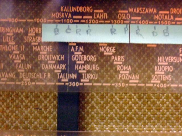 LW stations not only have long waves, but also a long lifespan. In a listening test in January 2014, I found that five of the stations of 65 years ago still exist: Allouis, BBC4, Warszawa, Kalundborg (broadcasting in DRM since 2006), and Moscow. I also noticed that the dial is accurate to well within one channel separation. To find an LW station, you can put the dial on the wavelength, and then just tune for best sound. You hear Cesky Rozhlas, recorded 11/01/2014, a station that ceases operation on February 28, 2014. LW stations not only have long waves, but also a long lifespan. In a listening test in January 2014, I found that five of the stations of 65 years ago still exist: Allouis, BBC4, Warszawa, Kalundborg (broadcasting in DRM since 2006), and Moscow. I also noticed that the dial is accurate to well within one channel separation. To find an LW station, you can put the dial on the wavelength, and then just tune for best sound. You hear Cesky Rozhlas, recorded 11/01/2014, a station that ceases operation on February 28, 2014. |
A few months later I  started to work on it and observed a few shortcomings that are quite common for this model. First, there is some damage to the woodwork of the side panel; actually, the cabinet bottom showed clear signs of moisty storage. Second, the radio was motorboating; by this we mean a putput like sound, that actually is a very low frequent oscillation. Third, the EM34 eye is dead. Fourth, the tuning string was defective so turning the tuning knob did not move the dial pointer. Finally, the radio was rather dusty from the inside.
I started to pull the chassis out of the cabinet; in this model and the similar BX591, BX480, etc, the speaker board is connected to the chassis so it is not necessary to unsolder the speaker wire or disconnect the EM34 or dial lights. The chassis looked a bit dirty, but a tooth brush and vacuum cleaner made it look like the picture on the left.  The dial chord is a rather contrived affair in this radio. While some radios have just a single string running over the tuning knob, condenator, and the pointer, Philips uses four wires here. Two drive the tuning condensator from the central axis, and two others drive the dial pointer. I found out that the condensator fuctioned OK, but the connection to the pointer was missing because chord CD was broken (see picture). I produced a new CD and managed to mount it, in about three quarters. Bad luck, after all this work chord AB broke, and I had to do it again. Perhaps I did something wrong, but I think that the original stringing schema gives the risk of the wire AB running off the pulley. In my third attempt I made a slight twist so that CD keeps AB in place. At least I can now say that I am my town's most experienced BX594 restringer.
Now for the motorboating.
 The usual cause is failure of C3, an electrolytic capacitor that is usually dried out and capacity-less after 60 years. The rattling cap C42 and coupling cap C40 should be replaced in any case, because any paper capacitor is dangerous in these places. Perhaps replacing C3 and C42 would be easier if I had removed the speaker, but it turned out to possible also while working under the speaker. There is just enough space there to cut off the cap lead with a plier, and then, because the new caps are so much smaller, there is enough room to solder them in place. The coupling cap (right) C40 is found under the output tube, and of course Philips managed to put it in a quite unreachable place.
The tubes measures as usable, except for one of the EAF42s, which I replaced. Then it was time to put everything back in place and connect an antenna. The radio played immediately, but I had to reduce the scratching by cleaning the volume and tonality pot.