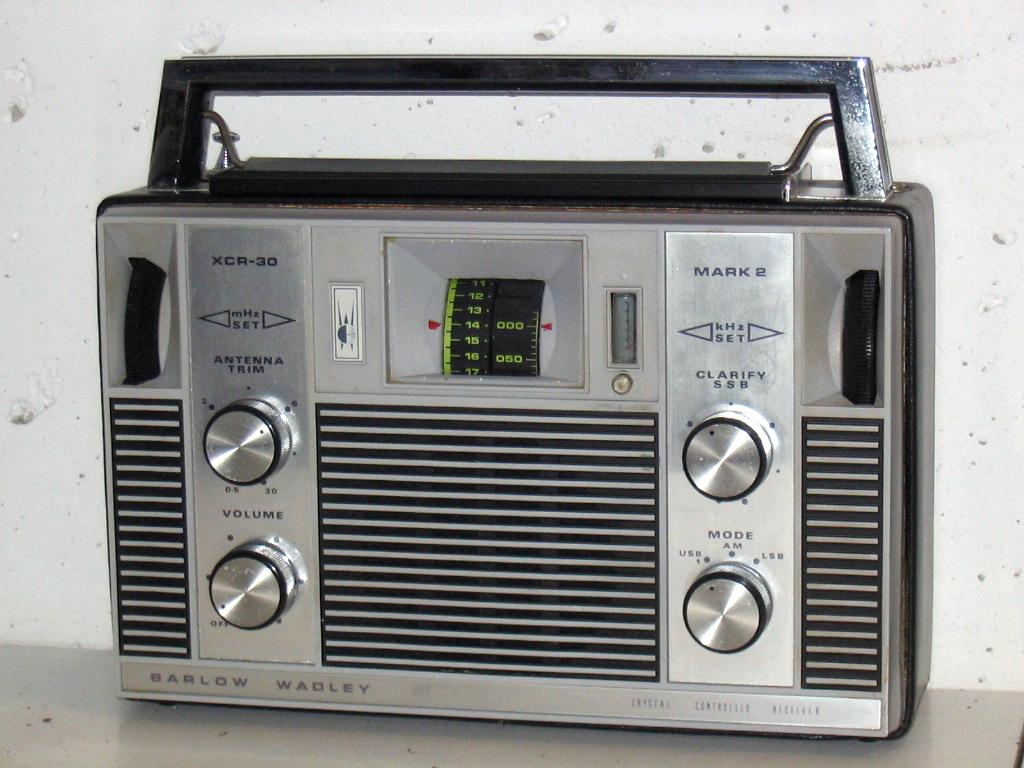
 The portable radio depicted on the left may not look very
much different from radios you could find in the nineteen seventies.
But first appearance is often deceiving;
the radio is the famous Barlow-Wadley XCR30 shortwave set.
It turned the radio listening world upside down
with its introduction in 1973,
and many people who had one at that epoch
(and those who had heard of it but could not afford it)
still fall silent when they hear the name.
The portable radio depicted on the left may not look very
much different from radios you could find in the nineteen seventies.
But first appearance is often deceiving;
the radio is the famous Barlow-Wadley XCR30 shortwave set.
It turned the radio listening world upside down
with its introduction in 1973,
and many people who had one at that epoch
(and those who had heard of it but could not afford it)
still fall silent when they hear the name.
But also some negative remarks about its performance
are in place.
In this short article I want to explain what was so special about it,
how its makers succeeded to give it its extraordinary qualities,
and how we can look back upon it now.
 The design of home entertainment equipment is usually quite simple:
a typical radio may have a radio-frequent amplification stage or not,
then follows a frequency converter
that maps the required station to one preselected frequency
(the Intermediate Frequency, for example 455kHz),
and this frequency is amplified, detected, and there is the audio.
Frequency conversion is done by mixing the signal
with the output of an oscillator, the local oscillator;
tuning a station requires to change the frequency of this LO.
The stations people want to receive are often relatively strong,
usually among the strongest around,
and stations remain in the air year around
so that the listeners can find their favorite three or four programs
easily on their dials.
The design of home entertainment equipment is usually quite simple:
a typical radio may have a radio-frequent amplification stage or not,
then follows a frequency converter
that maps the required station to one preselected frequency
(the Intermediate Frequency, for example 455kHz),
and this frequency is amplified, detected, and there is the audio.
Frequency conversion is done by mixing the signal
with the output of an oscillator, the local oscillator;
tuning a station requires to change the frequency of this LO.
The stations people want to receive are often relatively strong,
usually among the strongest around,
and stations remain in the air year around
so that the listeners can find their favorite three or four programs
easily on their dials.
When a shortwave receiver is constructed, problems have to be solved that have to do with mirror frequencies, weak signals, and stability. Mirror frequencies occur because during the mixing, not only the desired frequency is transformed to 455kHz, but so is the frequency 910kHz higher. If the desired station is weak and the other frequency is strong, interference with prohibit good reception. Problems due to mirror frequencies can be solved using higher intermediate frequency, or double mixing.
The stability problem has to do with finding a desired frequency among a lot of stations, and finding your station back the next day, even if you are not sure it is on the air. This is due to the difficulty of precisely setting the frequency of the local oscillator. On medium wave, if you want to hear a station on 1000kHz and you are 1% off, you are 10kHz away which is about 1 station further. On shortwave, if you tune to 13.500 kHz and you are 1% off, the difference is 135kHz and you are 27 stations further (channel separation is 5kHz on Short wave).
Accurate oscillators can be obtained using crystals,
but these oscillators are not tuneable,
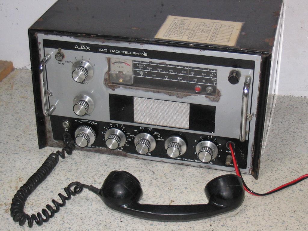 so the radio would need a crystal
for each frequency that you want to receive,
as in this ship transceiver
and this simpler Ajax A25
Trawler set (photo).
Another solution uses a crystal oscillator as a reference oscillator;
the Siemens E566
provides a fixed crystal oscillator
that can be heard at each multiple of 100kHz on the dial.
A quite complicated two-stage mechanism
allows to tune the radio reliably at 1kHz precision.
The Siemens was among the best receivers that were on the civil market;
the crystal reference oscillator and double conversion are useful principles,
but have to be combined with high precision construction
and this made the receiver expensive (40.000 guilders).
so the radio would need a crystal
for each frequency that you want to receive,
as in this ship transceiver
and this simpler Ajax A25
Trawler set (photo).
Another solution uses a crystal oscillator as a reference oscillator;
the Siemens E566
provides a fixed crystal oscillator
that can be heard at each multiple of 100kHz on the dial.
A quite complicated two-stage mechanism
allows to tune the radio reliably at 1kHz precision.
The Siemens was among the best receivers that were on the civil market;
the crystal reference oscillator and double conversion are useful principles,
but have to be combined with high precision construction
and this made the receiver expensive (40.000 guilders).
The principle behind the Barlow-Wadley was known since the late forties;
it was invented by Trevor Wadley, but patented!
The famous Racal RA-17 radios for the Brittish army used the principle,
but no factory was allowed to market it for the public.
In the early seventies the patent expired and Barlow decided
to implement it in a low profile (well, almost...) radio.
The same receiving principle was also applied in the FRG7.
 What is triple conversion, what do we need it for and why does the triple-conversion Barlow-Wadley need five mixers?
The solution to the stability problem is so simple that it is not surprising that somebody came up with it already in the nineteen forties.
We apply two stages of mixing, and cancel drift in the first LO by reusing its output in the second stage.
Indeed, the mixing signal is also mixed with the output of a crystal oscillator.
In this way, even if the LO drifts, the signal obtained after two mixing stages is exactly what it must be.
What is triple conversion, what do we need it for and why does the triple-conversion Barlow-Wadley need five mixers?
The solution to the stability problem is so simple that it is not surprising that somebody came up with it already in the nineteen forties.
We apply two stages of mixing, and cancel drift in the first LO by reusing its output in the second stage.
Indeed, the mixing signal is also mixed with the output of a crystal oscillator.
In this way, even if the LO drifts, the signal obtained after two mixing stages is exactly what it must be.
To see this in more detail, first suppose you want to receive a station exactly between two integer MegaHertzes, say at 14.5MHz. As you can see in the block diagram, the incoming signal is amplified in an RF Amp (TR5), upconverted to 45 Mhz in the Second balanced mixer, amplified in the 45MHz Amplifier (TR7), and downconverted in the Third balanced mixer to 2.5 MHz. The oscillator frequency we need in the second mixer is 30.5 MHz (because we increase frequency by that amount) and the one in the third mixer is 42.5MHz (we decrease by that amount).
Now what happens if the LO drifts and the 30.5 comes out a little too high? Then our signal after mixing ends up a little above 45MHz, but we could still arrive at 2.5MHz in the third mixer if we would increase the mixing frequency there by the same amount! So, drift is not a problem per se if we manage to keep the difference between the two mixing frequencies at exactly 12MHz. To this end, the mixing frequency for the third mixer is obtained by mixing the mixing frequency in the second mixer with harmonics of a 1MHz crystal oscillator (TR1); this happens in the first balanced mixer. So you see in the block diagram that the output of the Local Oscillator (TR6) goes into the second mixer and into the first mixer. The second mixer processes the radio signal, the first mixer produces the necessary mixing frequency for the downconversion. As a result, the 14.500MHz radio signal will end up at 2.500MHz exactly, regardless drift of the LO, assuming the crystal oscillator is exact.
A similar thing happens if you want to receive 3.5MHz, 7.5MHz, 22.5MHz, and so on, but what if your receiving frequency does not end in .500? It seems as if your superb drift cancellation makes it impossible to tune your radio by moving the Local Oscillator. Now here comes the really dirty thing. The amplifier and mixer do not forward just a single frequency, but have a bandwidth of a bit more than 1MHz. So, with the described operation, the RF part does not only map the 14.500 signal to exactly 2.500, but actually maps all frequencies between 14.000 and 15.000 to frequencies between 2.000 and 3.000 kHz. Exactly. And now the whole thing is followed by a classically designed receiving part that covers this band of 2-3 MHz. That is what we need the tunable 2-3MHz amp for (TR8), which would be called an RF stage in the classical set. It is followed by a self-oscillating mixer number 4 and a 455kHz amplifier (TR10-12). And because this thing I call a classical set only has to receive one band (2-3MHz) of reasonnably low frequency, it can be constructed at low cost with sufficient precision.
For the guys who want to receive SSB or morse, a BFO is built in with mixer number 5.
That's elementary, dear dr Watson...

It is quite easy to dismantle the set for most repairs,
because back and front can be removed by loosening just a few screws.
However, for working on the cabinet this isn't enough,
so I had to take the chassis out of the cabinet,
and this requires to unsolder a few earthing connections.
The service manual discourages you to do so,

 but sometimes one must,
and this is what a bare XCR30 chassis looks like.
On the left picture you can see the crystal oscillator
mounted on a separate piece of PCB.
I tried to remove as much of the corrosion as was possible
without damaging the cabinet;
replacement of the battery holder wasn't difficult at all.
but sometimes one must,
and this is what a bare XCR30 chassis looks like.
On the left picture you can see the crystal oscillator
mounted on a separate piece of PCB.
I tried to remove as much of the corrosion as was possible
without damaging the cabinet;
replacement of the battery holder wasn't difficult at all.
If you have to maintain one of these sets ever, remember this:
never try to align the 42.5 and 45MHz circuits outside a laboratory!!
The reason for this is in the tricky operation of the 45MHz amplifier.
As I said, it has circuits with a 1MHz bandwidth,
but when you listen to one station, you use only 5kHz of this.
Sometimes, people tune one station,
and then align all coils to maximum output.
But this alignment by ear
concentrates all amplification in this stage
to the single frequency you are listening to at that moment.
A painful waste of a nice receiver,
which will not be able to receive any statios anymore
that are located at a different part of this frequency band.
Alignment can only be done with precise instructions and a wobbulator,
making the entire band pass visible on an oscillator screen.
To go over the other controls briefly:
Mirror frequencies in the classical sense (stations that differ from the target frequency by twice the Intermediate frequency) are fully absent. Indeed, the first IF is 45MHz, which means that mirrors are in the FM range and these are adequately suppressed by the filter circuitry in the RF amplifier.
But still, you hear a lot of spurious stations, and a lot of noises and whistles, too. First, the spurious stations. If your target frequency is weak you may hear stations that are exactly 1 MHz higher or lower. Indeed, they are insufficiently suppressed by the RF tuning circuit and passed in the flanks of the pass curve of the 45MHz amplifier; in the third balanced mixer they meet other harmonics of the crystal oscillator and get into the tunable amplifier, competing with the desired frequency. Of course, by the various circuits they are supposed to be suppressed a lot, but still they are noticable if the original signal is very strong.
The other problem comes from the transistor amplifiers that amplify a complete band of 1MHz wide at the same time. Here, receiving a weak station, you are bothered by strong stations in the same MHz-range as your target frequency. While you try to get the best out of your weak station, your IF amps are dealing with strong signals simultaneously, that are only suppressed later in the 2-3 MHz amplifier. The unwanted mixing that occurs in transistor amplifiers causes noise and whistles.
Then, there is a problem altogether with weak stations.
Most DX-ers would agree that good reception starts
with a good antenna, but with the Barlow-Wadley this isn't the case.
It was designed to work optimally with its built-in whip antenna,
and connecting a stronger antenna like a longwire
will overload the RF and 45MHz stages considerable.
So, you cannot improve reception of a very weak station
by building a very good antenna.
 I realise that it is possible that the set I worked with is a bit sick,
it could be misaligned or have other problems
that cause it to work less good than it should.
I realise that it is possible that the set I worked with is a bit sick,
it could be misaligned or have other problems
that cause it to work less good than it should.
My own BW in 2014, again surprised me with its dial accuracy and sensitivty. On its whip antenna alone, it clearly reproduces stations (even SSB) coming in only noisily on the Philips D2999 with an outdoor long wire. But again, amidst the various stations, I heard a plethora of noise peaks, whistles, and ghost stations.
 There is also a version with FM, with the FM tuning unit on top.
The unit could also be bought separately and added to an existing set.
Wim reports on the
Transistorforum
that the Barlow Wadley is notorious for its bad Intermodulation properties,
due to very strong HF amplification.
A station you want to hear,
should not be weaker that 60dB below the strongest station in the range.
The Intermodulation causes so abundantly spurious stations,
that serious DX-ers have turned away from the Barlow Wadley.
There is also a version with FM, with the FM tuning unit on top.
The unit could also be bought separately and added to an existing set.
Wim reports on the
Transistorforum
that the Barlow Wadley is notorious for its bad Intermodulation properties,
due to very strong HF amplification.
A station you want to hear,
should not be weaker that 60dB below the strongest station in the range.
The Intermodulation causes so abundantly spurious stations,
that serious DX-ers have turned away from the Barlow Wadley.
But my tentative conclusion is: a nice beach set, but for home listening it cannot compete with more serious receivers like the Philips D2999 or Grundig Satellit 2100.