295
Item nr.
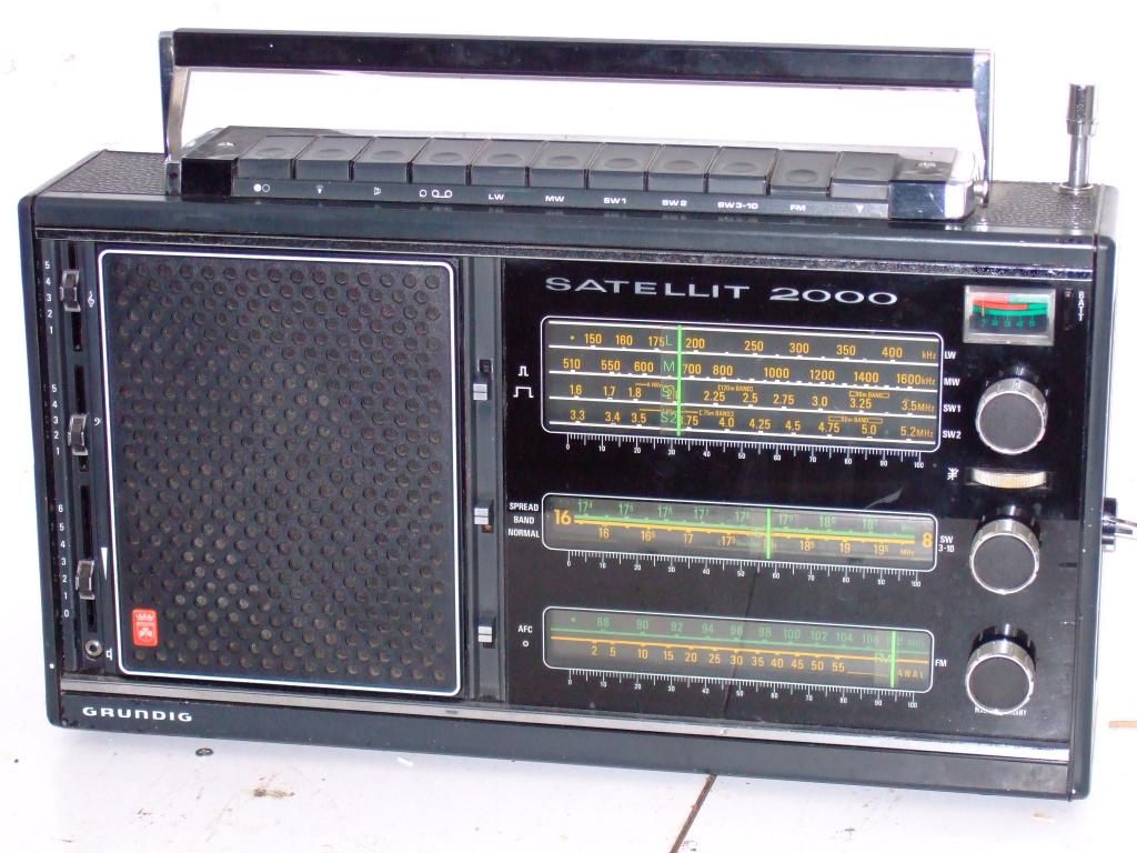
Shortwave listener's dream
| Production | Germany, 1973. |
|---|---|
| Bands | LW (150-400kHz), MW (510-1600kHz), SW1 (1.6-3.5MHz), SW2 (3.3-5.2MHz), SW3 (5.0-6.5MHz), 49m (5.9-6.25MHz), SW4 (6.6-8.4MHz), 41m (7.00-7.30MHz), SW5 (8.2-10.4MHz), 31m (9.40-9.95MHz), SW6 (10.5-13.2MHz), 25m (11.60-12.15MHz), SW7 (13.0-16.3 MHz), 19m (14.95- 15.70), SW8 (15.5-19.5MHz), 16m (17.4-18.15MHz), SW9 (18.5-23.0MHz), 13m (19,90-21.90MHz), SW10 (23.5-30MHz), 11m (25.4-26.5MHz), U/FM (88-108MHz). |
| Semi- conductors | 27 transistors and 14 diodes. |
| Cabinet | Plastic. Size 46x24x12 cm. Weight 6.3kg. |
| Power | AC or Batt (9V, 6xD). |
| Documents | Schema, dial chord diagram. |
The design is a double conversion superhet to get rid of mirror frequencies. A nice feature is that the ten SW bands cover the entire 1.6 to 30MHz frequency range, but in SW band 3 to 10 there is the possibility to change to a part of the band, corresponding to a broadcast band. With the FM also present, this brings the total count of bands to 21.
A nice addition is the SSB Zusatz, a small unit containing a BFO to overhear Single Side Band transmissions.
| Obtained | 4/2007 from Johan van Gend. |
|---|---|
| Condition | 8. |
| Disposed | Sold 6/2013. |
| Sound sample | PLAY SOUND Joan Osbourne sings What if God was one of us. The nice message of Christmas is: He is! |
 If you ever find yourself in the need to pull the chassis, as I did, you might find the following helpful.
Step 1: Back. Take out three long screws on the top edge of the back, and four shorter screws on the back side of the bottom. Remove back panel; radio looks like picture on the left.
Step 2: Pushbuttons. Remove two screws besides the pushbuttons on top, and remove push button assembly and carrying handle.
Step 3: Knobs. For the nine knobs on the front panel, just pull. The band switch in the side panel is secured to its axis with a little screw that you must first remove through the back side of the radio.
 Step 4: Antenna.Pull loose the red antenna wire and unscrew the two bolts fixing antenna base. Now carefully pull the antenna downward and out.
Step 5: Screw. On the bottom, there is a screw near the front edge, but this one need not be removed. Inside the radio there is a screw next to the FM tuner, which you must take out. You are done!

 Pull the chassis carefully out of the cabinet, and to your surprise, find parts of a Greek telephone card from 1999 inside (photo left). You can see the entire chassis (right) and try to count if all 27 transistors are really there.
Fortunately, my problem with the FM dial chord slip was minor: I didn't have to restring the chord, but only had to lubricate the FM tuning condenser to make the whole thing going again. To put the radio back, revert all steps from 5 to 1.